
Packaging Line Layout Checklist
A machine footprint can fit while replenishment and maintenance remain blocked. Review the plan, elevation, delivery route, interfaces and task rehearsal against the actual configuration drawing.
| Input or item | Value or source | Why it matters |
|---|---|---|
| Plan view | Measured room and flow drawing | Show material and people movements |
| Elevation | Clear height and overhead obstacles | Review upper feeding and removal paths |
| Delivery route | Actual shipping dimensions | Check doors, turns and assembly access |
| Interfaces | Mechanical and control schedule | Assign each connection an owner |
| Task rehearsal | Operations and maintenance procedures | Expose temporary space requirements |
Choose the next review for your project
Use the records below to identify the unresolved decision. These related pages explain the corresponding configuration, measurement or service scope.
On This Page
Input drawings: map material, people and replenishment
Show where bulk product arrives and where finished packs have to go. Include existing conveyors, columns, doors and fixed equipment, with clear dimensions and ceiling restrictions. A machine footprint by itself misses the interfaces and the access that make a line usable in the intended location.
Think through the operator positions, film or pouch replenishment, cleaning and the removal of format parts. Elevated weighing equipment may need a platform arrangement, and that changes the overall space requirement. Request a drawing of the actual proposed configuration. Dimensions from a related model or a workshop photo are no substitute.
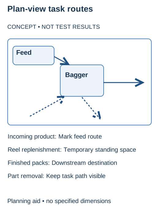
A packaging layout should show how product, packaging materials, finished packs and people move through the area. Start with the upstream supply and the downstream destination, then place the bagging and dosing equipment between them. Add columns, doors and existing services. A machine outline alone does not show the space needed to operate and maintain a working line.
Mark the routine access points for reel loading, product replenishment, controls and removal of contact parts. The supplier can provide the maintenance and service envelopes. Show the path used to bring large parts or tools into the area. A blocked access route is far cheaper to fix on a drawing than after the equipment has been set down between existing machines.
Put the containers and handling equipment that will really supply the line on the drawing. Where relevant, include the film trolley, pouch cartons, ingredient containers and finished-pack handling. Mark their temporary positions during replenishment, not only where they are stored. An aisle that is clear in steady running may be blocked each time an operator opens a carton or brings a new reel to the machine.
Trace one representative material from its storage point to the point of use, and note where it crosses finished goods, rejected product and people. Operations staff can tell you whether the proposed route fits the planned batch schedule. Frequent small deliveries and occasional large replenishments create different traffic patterns. The layout should follow the intended operating method, not a generic picture of an empty room.
Input drawings: check elevation and delivery access
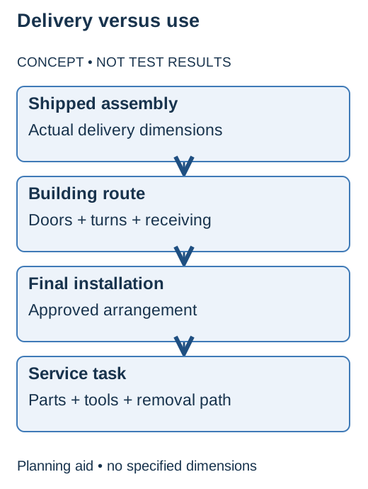
Compare the delivery dimensions and handling requirements for the actual equipment with your doors, turns and receiving area. Identify components shipped separately and the space needed to assemble them. Delivery access cannot be worked out from the final installed footprint. A platform or tall assembly may need a different handling plan from the bagger underneath it, and the responsible installation specialists must review that plan.
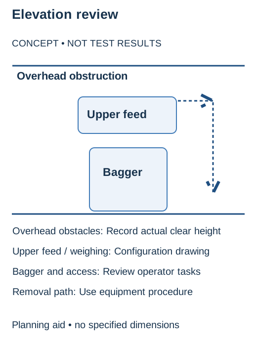
Record the clear height at the proposed location, including overhead services and obstructions a simple floor plan does not show. An elevation showing the feed connection, platform and maintenance access is worth requesting. If a component has to be lifted out for servicing, its removal path belongs in the review. A machine can fit under the ceiling when assembled and still lack the space the documented maintenance task needs.
Task rehearsal: operation, cleaning and component removal
Use the drawing to rehearse a reel change, a product change, a cleaning task and a component replacement. Where do removed parts, waste packaging and rejected product go? Those temporary activities should not sit on an essential access route. The layout has to support the work around production as well as the work during steady running.
Before you approve the drawing, check the dimensions against the site and record the revision. Identify the utility drops and who is responsible for preparing them. After any equipment or format change, review whether the access and transfer assumptions still hold. A good layout is a controlled project document that links the machine proposal to the real building and the real operating process.
Pick a specific task, such as removing an approved contact part or changing a forming component, and trace the access it needs. Note where tools and removed parts will be put. Keep that temporary workspace separate from product storage and routine traffic. The relevant staff can say whether the proposed access supports the documented procedure without moving unrelated equipment every time the task comes up.
Before final approval, have the responsible party verify the critical building dimensions on site, and mark the drawing's status. A preliminary proposal stays preliminary until the necessary interfaces and measurements are confirmed. Keep the approved revision where facilities, purchasing and the installation team can reach it. That turns the layout into a working coordination document, which helps avoid mismatched utility drops, inaccessible service points and changes after delivery that could have been prevented.
Complete the observation record
Use one unresolved-dimension list for the layout review, adding a location for each measurement rather than scattering assumptions across email comments. State whether the value came from a site measurement, supplier drawing or early estimate, and include its unit. Relate it to the exact configuration revision and the task that depends on it: moving a reel, reaching an inspection point, removing a contact part or delivering an assembly. Record the interface owner separately from the person verifying a building dimension. Do not fill unknown clearances with a generic allowance. The responsible installation and site specialists need to confirm the requirements for the actual equipment and location.
| Field | Your record | Keep with this record |
|---|---|---|
| Location / task point | ________ | Record the source, identity or agreed method. |
| Actual dimension / unit / source | ________ | Record the source, identity or agreed method. |
| Measured or estimated / verification owner | ________ | Record the source, identity or agreed method. |
| Proposed configuration drawing revision | ________ | Record the source, identity or agreed method. |
| Task to complete / temporary space | ________ | Record the source, identity or agreed method. |
| Mechanical or control interface / responsible party | ________ | Record the source, identity or agreed method. |
| Unresolved question / next evidence | ________ | Record the source, identity or agreed method. |
Responsibility closure: resolve equipment interfaces
Mark the utilities and any customer-supplied equipment on the drawing, and say who designs each connection. Check the delivery route into the building as well as the final position. Keep preliminary assumptions apart from approved dimensions. The responsible specialists need to review the structural, site and regulatory requirements for the installation.
Vertical packaging systems can put dosing equipment and platforms above the bagger. Confirm the ceiling restrictions, the overhead services and how the upper equipment will be fed. Plan view is not enough, so request the elevation drawing and mark the points where the customer needs access or lifting arrangements during installation and maintenance.
Document the transfer to inspection and downstream handling. Agree the pack direction, the discharge height and the signals needed between machines. If a bag must settle before another operation, write that down. The discharge conveyor will not necessarily provide it. When several vendors supply the line, give each mechanical and control interface an owner.
Show the finished pack's orientation and direction as it leaves the bagger. Confirm the transfer to any inspection conveyor, accumulation area or case-packing operation, and include how rejected packs will be handled and who can reach them. Bags behave differently from rigid containers. The receiving interface should therefore be reviewed with representative filled samples, not just a conveyor centreline.
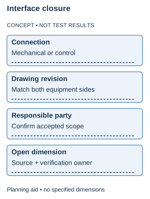
Assign responsibility for mechanical connections, control signals and shared operating conditions. If another vendor supplies the downstream equipment, set up a common interface schedule with drawing revisions and open questions. Two machines that each suit the job will not necessarily make a suitable line without integration work. The layout drawing should point to those interface documents. Then changing one conveyor does not leave the rest of the team working from an obsolete arrangement.
Responsibility closure: keep one unresolved-dimension list
If you do not yet have a full drawing, an early enquiry can include a marked sketch. Label its dimensions as measured or estimated, and name the person who will verify the critical values. Add photographs of the proposed location that show overhead and side obstructions as well as the floor area. Request a preliminary configuration envelope and an interface question list. The project can then move forward with the uncertain building information still visible. An approximate sketch is not an approved installation drawing.
Method and scope of this guide
This revision of Packaging Line Layout Checklist organizes the existing published review points into a buyer preparation record. The diagrams illustrate plan-view task routes, elevation review, delivery versus use, interface closure. They contain no measured trial results, approved engineering dimensions or acceptance thresholds. The empty record fields are prompts for project evidence, not a completed inspection. Source: the existing guide and the published Configuration Review and Sample Testing service descriptions, accessed October 8, 2026. Before sending physical samples, confirm receiving arrangements, quantity and costs. Keep any recommendation tied to the supplied material, proposed configuration and outstanding questions.
Frequently asked questions
Why can equipment fit the room but still be unsuitable?
An outline does not show replenishment, operating positions, removed parts or maintenance access. Rehearse those tasks on the proposed layout.
When is an elevation drawing needed?
Use it to review overhead obstacles, elevated feeding or weighing equipment, clear height and component removal paths that plan view cannot show.
How do delivery dimensions differ from installation dimensions?
Delivery involves the actual shipped assemblies, doors, turns and assembly space. The final installed footprint alone does not establish that route.
Who owns the interface to a customer-supplied conveyor?
Assign mechanical, control and operating-condition responsibilities explicitly between the relevant parties. Keep the common interface schedule linked to current drawings.
Explore the Equipment
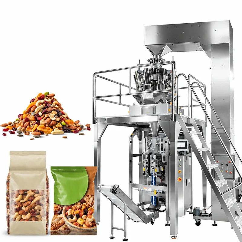
Vertical Form Fill Seal
Nuts & Dried Fruit Multihead VFFS
A nut-mix bag can be on weight and still hold the wrong ratio of ingredients. Configure this multihead VFFS line from your blend, coatings, target weight and bag size.
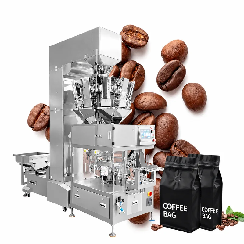
Premade Pouches
Coffee Bean Doypack Packaging
A valve or zipper too close to the pouch mouth catches beans and spoils the seal. Size this premade doypack line for coffee from your actual pouch, bean condition and fill weights.
What to send us
| Item | Why we need it | Example format |
|---|---|---|
| Dimensioned plan, clear height and obstacles | Place the proposed equipment against verified room information. | Dimensioned plan + elevation + obstacle photos |
| Product and finished-pack flow | Connect incoming material to finished-pack movement. | Marked product / packaging / people-flow sketch |
| Operation, maintenance and delivery access | Check the tasks that need more than a machine footprint. | Task sketch + delivery dimensions and route |
| Utility and equipment interface responsibilities | Assign the connections outside a single supplier’s scope. | Interface schedule: connection / owner / revision |
We reply within 24 hours.