
Coffee Bag Valve: VFFS Degassing-Valve Applicator and Leak-Test Guide
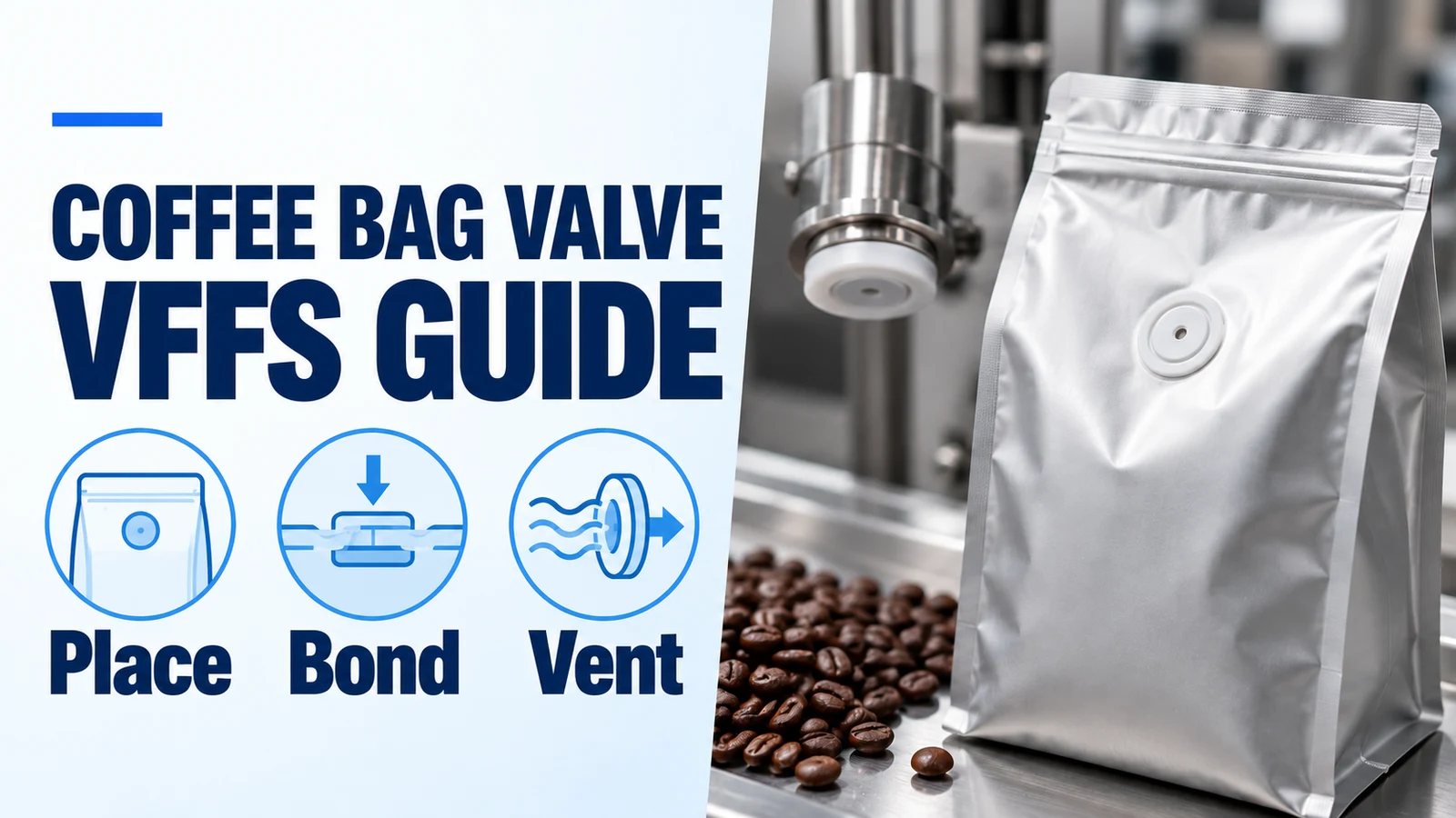
A misplaced coffee bag valve wastes film and filled bags. Match the VFFS degassing-valve applicator, punch and film, then separate valve function from leaks.
| Input or item | Value or source | Why it matters |
|---|---|---|
| Valve part and revision | Component supplier drawing | Defines side, aperture and attachment footprint |
| Film and sealing surface | Laminate supplier specification | Sets the compatible attachment interface |
| Position and total variation | Flat-web and filled-bag drawings | Checks clearance to folds and seals |
| Opening, reseal and flow | Selected component specification | Keeps separate functional acceptance criteria |
| Test method and limits | Buyer quality plan + supplier procedure | Defines sample handling and pass criteria |
On This Page
Define the valve, film and applicator as one interface
A VFFS coffee bag valve applicator needs a matched valve part, film opening and attachment process. Confirm those interfaces before approving a machine quote. This guide helps a roaster or packaging engineer prepare the position drawing and acceptance record for an inline degassing-valve project. It focuses on punch-and-apply control and test interpretation; the broader valve-selection guide covers supply routes and component choices.
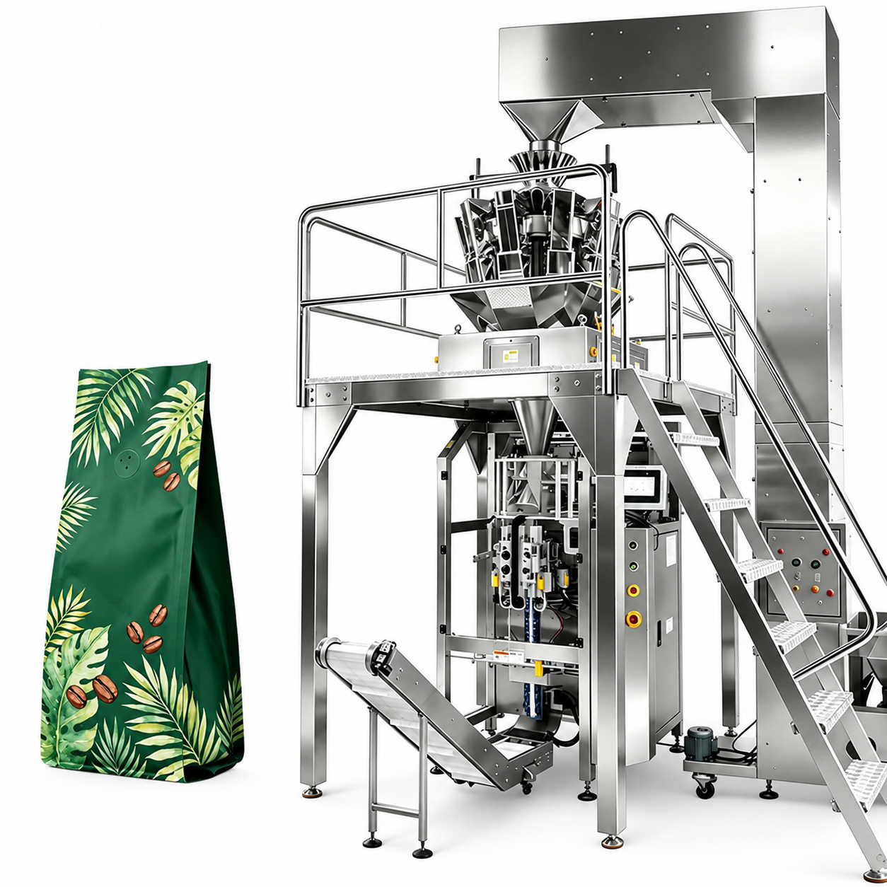
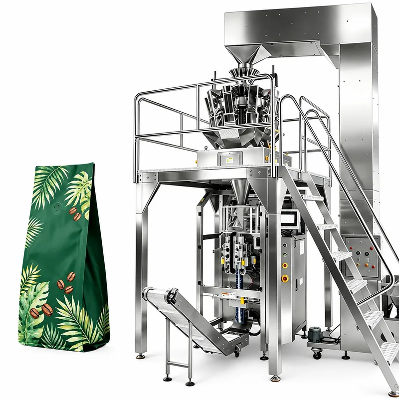
In the published coffee-valve VFFS configuration, the applicator works on roll film before bag forming. The coffee then enters the formed bag through the weighing and filling arrangement. That order matters: a valve attached correctly to a flat web must still clear the forming path and remain usable in the filled package. A photograph of a finished coffee bag cannot establish that the proposed module makes its exact construction.
Ask the quotation to identify the valve part and revision, which film face receives it, the opening geometry and the attachment technology. Record who approves each interface. Obtain the valve supplier's drawing and film supplier's sealing information together, then ask the machine supplier to identify the matching tooling and process window. A missing drawing is an unresolved purchasing input, rather than a reason to choose a convenient head setting.
- Coffee-valve VFFS configuration: review the published roll-film route
- Broader degassing-valve selection and supply-route comparison
Choose the mounting side before choosing the pressing head
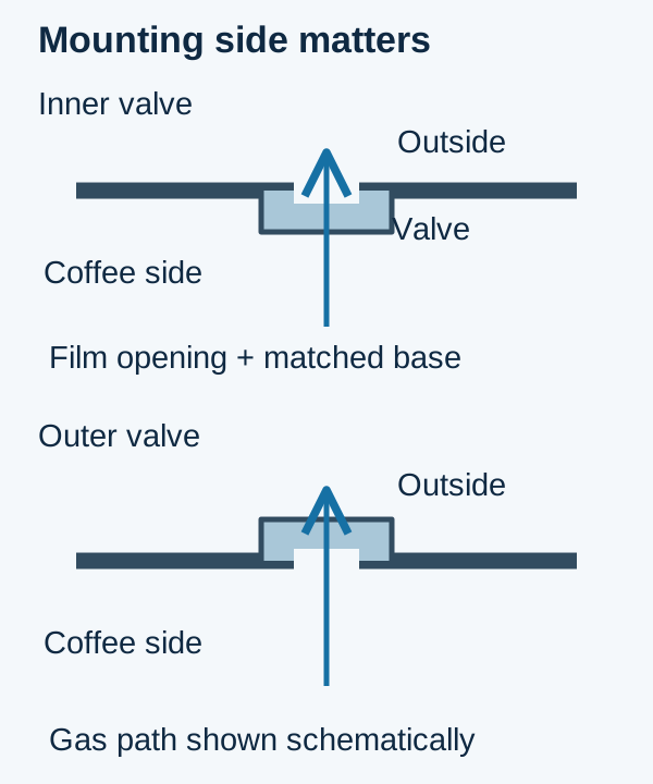
Inner and outer describe the valve's location relative to the laminate. They do not specify one universal welding method. An inner valve sits on the product side, beneath the laminate; an outer design presents its body outside. Follow the component drawing for the route from the coffee headspace through the film opening and valve. Do not reverse a component merely to hide it behind artwork.
Heat sealing and ultrasonic welding are documented attachment categories. Our published coffee-valve configuration describes hot-press application; a request for ultrasonic attachment requires a separately confirmed proposal. Matching the valve body material to an attachment process is only part of the decision. The laminate surface, sealing layer, tool contact geometry and support beneath the film must also suit that exact assembly.
The comparison below identifies purchasing checks for each route. For an inner valve, inspect whether forming loads or the filled product obstruct the inlet. For an outer valve, inspect downstream contact and handling clearance. Neither route earns a shelf-life or leak-tightness guarantee from its mounting side. Keep the approved component and finished-package sample together so a later substitution triggers an interface review. Ground coffee adds a fines question: request the appropriate filter construction and evaluate the actual product rather than assuming a whole-bean valve is equivalent.
| Decision | Selection and interface to confirm | Dominant Failure Mode & Prevention |
|---|---|---|
| Inner mounting | Component designed for the product side. Confirm: Inlet, filter and forming clearance. | Obstructed inlet or folded base; check filled samples and the component drawing |
| Outer mounting | Component designed for outside attachment. Confirm: External footprint and handling clearance. | Rim damage or snagging; verify contact through the downstream path |
| Thermal attachment | Matched heat-sealable component and film. Confirm: Tool face, support and allowed process window. | Incomplete ring or distorted film; qualify the matched setup |
| Ultrasonic attachment | Separately confirmed compatible assembly. Confirm: Component/laminate and proposed tooling. | Incompatible weld interface; review samples and quoted scope |
Calculate position margin from the valve edge
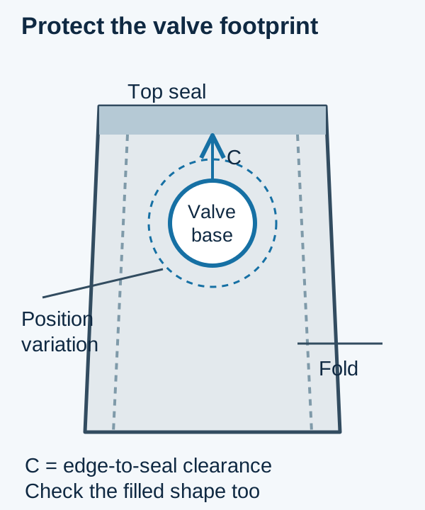
Measure clearance from the complete valve and attachment footprint to the nearest prohibited feature. A centre coordinate alone cannot show whether the attachment ring overlaps a fold, zipper or seal. Mark those features on both the flat web drawing and a filled bag, including the direction in which the web travels.
Use a conservative first check: C_min = C_nom − E_web − E_apply − E_form. Here C_nom is nominal edge-to-feature clearance in millimetres; the E terms are the maximum adverse contributions assigned to web registration, valve placement and forming movement. Add only independent contributions. If the supplier gives one total placement tolerance that already includes web tracking, do not subtract web variation again.
Hypothetical drawing example: C_min = 20 mm − 3 mm − 2 mm − 2 mm = 13 mm. If the component/tooling supplier requires 15 mm clear space for this example assembly, 13 mm is insufficient. Relocate the valve or reduce the confirmed tolerance stack before accepting the layout. These assumed values explain the calculation; obtain the actual clearance and tolerances for your valve, film and tooling.
Rule of thumb: if C_min is below the supplier's required clearance, reject that position even when the nominal centre looks correct. Also reject a position whose gas path becomes obstructed after filling. Evaluate the smallest and largest intended fills, restart samples and film-roll changes. A flat layout with adequate seal clearance can still fold across the valve when the retail bag takes its final shape.
Separate the film opening from attachment pressure
Specify the completed opening and the tool setup separately. The source configuration describes punching before application, but it does not publish a universal punch depth. A stroke setting depends on the punch, backing arrangement, clearances and actual web construction. Film thickness alone cannot define the correct machine setting.
Request the specified aperture shape, size and position, together with the accepted appearance of its edge and the means of accounting for removed material. For a through-punched opening, the acceptance question is whether the intended layers are cut cleanly without unintended damage outside that opening. For a different supplier-designed vent path, use its own drawing and inspection criteria. Do not turn a through-hole requirement into a general instruction to score only part of the laminate.
Then assess the attachment ring. Record the approved tool identity, contact area, support arrangement and process recipe. A larger pressing force cannot compensate for an incompatible sealing surface or an off-centre opening. For thermal attachment, obtain the component and laminate suppliers' allowed process window; for another process, obtain its corresponding controls. Keep temperatures, dwell and force fields blank until they are specified for the assembly.
Review retained samples after stable running and after interruptions. Look for film distortion, incomplete attachment around the perimeter, contamination and interference with the forming path. Ask how the proposed line detects or handles a missing or misapplied valve, and record whether that function is included. An agreed reject-handling demonstration belongs in the acceptance scope; it must not be assumed from an applicator photograph.
Keep gas release, resealing and package leaks distinct
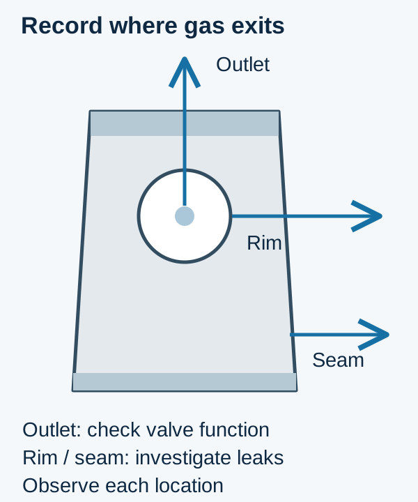
A coffee degassing valve intentionally releases gas through its outlet. Distinguish that intended flow from leakage around its attachment rim or through a bag seam. Record where gas exits as well as the test conditions; a single observation of bubbles cannot establish whether the package passes.
Keep four separate records. The opening record identifies the pressure difference at which the selected component begins the specified outward flow. The resealing record evaluates closure under the component supplier's defined conditions after venting. The attachment-integrity record examines unintended paths around the mounted base and aperture. The bag-seal record examines the longitudinal and transverse closures. Flow capacity is another component specification: opening at a stated pressure does not establish how much gas the valve can pass under the required conditions.
Use the chosen valve's supplier procedure to define test gas, orientation, conditioning, pressure progression, flow criterion and acceptance limits. Pressure difference means internal pressure minus external pressure, with the sign convention recorded. An opening-pressure range from a different valve is not the setting for this component, and it cannot be reused as a closing-pressure limit. Roasted-coffee condition, fines and filled-package handling belong in the evaluation because a clean, loose component and an installed valve face different conditions.
ASTM F2096-11(2019) addresses gross-leak detection by internal pressurization. Its public scope describes a destructive method; it does not supply a universal coffee-valve pass pressure. A functioning outlet can release gas during a package assessment, so agree how that intended path will be identified and accounted for. Any method adaptation needs validation before results are described as conforming to a standard.
ASTM F88/F88M-23 addresses the force needed to separate a strip containing a seal and the specimen's failure mode. It supports a separate seal-strength question with a defined specimen and fixture technique. It does not establish valve opening, resealing or whole-package gas tightness. Have the quality team select the applicable methods and acceptance criteria before the trial, then retain the conditions beside each result.
Use a trial record that keeps the sample identity intact
Label each sample before separating it for the different tests. Record the coffee lot and form, roast-to-pack interval, valve lot and revision, laminate revision, bag drawing, fill mass and machine recipe. Associate each reading with its method and limit. A value without a sample identity or a pass criterion cannot close an acceptance item.
Collect records for startup, stable running, a planned stop and restart, and a representative roll or format change. Agree the sample plan and run duration with the quality team rather than borrowing an arbitrary count from another project. Note whether the valve position changes at those transitions and whether the reject-handling response matches the quoted function.
The downloadable CSV below provides blank rows for those run stages and separate fields for position, aperture, attachment, opening, resealing, valve flow and bag-seal checks. It contains no preset pressures, temperatures or pass results. Enter the procedure reference and agreed limit before entering measurements. Keep untested combinations open, and attach photographs to the corresponding sample identifiers in your own records.
For a factory acceptance test, request the accepted setup revision and labeled retained bags along with the record. If nitrogen flushing is included, define its own supply and package-assessment scope. A gas-flush option and a one-way valve perform separate jobs; neither establishes coffee storage life without finished-package evidence. This handoff lets purchasing distinguish a completed demonstration from a quoted option awaiting evaluation.
Compare reject and downtime costs over the same period
Compare the application routes using accepted bags and the same production period. Include valve and film consumption, attachment-related rejects, setup scrap, changeover labor, inspection, tooling and maintenance. Keep coffee loss separate from empty-web scrap: a rejected filled bag consumes different inputs from an opening rejected before filling.
Accepted output = accepted bags ÷ observed minutes. Hypothetical trial arithmetic: 9,800 accepted bags ÷ 250 elapsed minutes = 39.2 accepted bags/min. State whether those minutes include the recorded interruptions. If elapsed time already includes downtime, do not subtract it again through another availability factor. This arithmetic describes the counting method, not the speed of an offered machine.
For a hypothetical monthly requirement of 100,000 accepted bags and a total reject fraction r = 0.02, attempted bags = 100,000 ÷ (1 − 0.02) = 102,040.8, rounded up to 102,041 whole attempts. The planning allowance is therefore 2,041 rejected attempts under those assumptions. Assign unit costs only after identifying which losses occur before and after coffee filling. The assumed reject rate is a worksheet input, not an expected result.
Use one consistent monthly boundary: total cost = attempted-bag consumables + filled-product losses + setup labor + inspection + energy + maintenance + monthly capital allocation. For example, four assumed changes of 0.5 hour consume 4 × 0.5 = 2 labor-hours before multiplying by your actual labor rate. Compare both routes with identical output, staffing boundaries and capital-allocation periods. A lower valve purchase price may leave tooling, film damage or inspection work elsewhere in the line; request those scope items explicitly.
What to send for an applicator configuration discussion
Send the valve drawing and part revision, the bag layout with a marked valve footprint, and the intended laminate specification. Include whether the project handles whole beans or ground coffee, the fill range and the planned production changes. If any item is undecided, mark it unknown so it stays visible in the quotation discussion.
Attach your proposed test record or list the missing limits using the fields above. Ask the proposal to identify the supplied attachment method, tooling, quoted inspection and reject functions, and the sample combinations to be evaluated. Use the enquiry below to share those project details and discuss the configuration; arrange physical samples separately. Keep the accepted drawing and trial conditions with the purchase scope so later valve or film substitutions receive the same review.
| Item | Why we need it | Example format |
|---|---|---|
| Valve part, revision and drawing | Identify mounting side, aperture and attachment interface | Component drawing PDF with part revision |
| Film specification and bag layout | Review the footprint and clearance calculation | Laminate data + dimensioned web and filled-bag drawing |
| Coffee form, fill range and run pattern | Define sample combinations and production changes | Whole beans or ground coffee; planned fills and changes |
| Functional and package-test requirements | Keep opening, reseal, flow, attachment and bag seals distinct | CSV record with procedures and limits, or unknown fields |
Method and sources
Updated October 2026. This application and test-planning guide combines the authorized company coffee-valve configuration with component-category information from the valve OEM technical literature reviewed on 19 October 2026. That literature distinguishes inner and outer constructions, heat and ultrasonic attachment, and filtered component variants. Those categories guide the interface questions here; the exact component drawing controls a project.
The standards discussion uses the publicly available scope and significance sections of ASTM F2096-11(2019) and ASTM F88/F88M-23, checked on 19 October 2026. It describes what those methods assess, rather than reproducing their full procedures or assigning acceptance limits. Position-margin, output and monthly-loss examples are explicitly hypothetical calculations. The blank record collects buyer and supplier inputs; it contains no measured results. Catalog images show configuration context, and the diagrams explain relationships without engineering dimensions.
Technical Reading
- ASTM F2096-11(2019): gross-leak detection by internal pressurization — Public scope and significance only; method suitability and acceptance criteria require review.
- ASTM F88/F88M-23: seal strength of flexible barrier materials — Seal separation force and failure mode; separate from valve functional testing.
Explore the Equipment
Vertical Form Fill Seal
Coffee Bean Valve-Pouch Packaging
A misplaced or poorly attached degassing valve can spoil a run of coffee bags. Specify this weigher and VFFS valve line from your valve drawing, film, roast and weight.